8 CIVIL WORKS GUIDELINES FOR MICRO-HYDROPOWER IN NEPAL
site to site and project to project. Project layout arrangements
shown in Figure 2.0 are combinations of weir and intake,
intake canal, spillway, gravel trap, approach canal, settling
basin, headrace canal/pipe, forebay, penstock and the
powerhouse. The five layout arrangements shown in the
figure are briefly discussed herein.
Layout 1
Layout 1 is a standard type of micro-hydro project layout
arrangement with most components included. This type of
project layout arrangement is used in case of higher design
flows (300 l/s or above) from a relatively large river. Due to
the large flow that can enter into the water conveyance system
its management as well as sediment exclusion has higher
importance. Thus, all standard structures of a micro–hydro
project are required.
Layout 2
The difference in this layout compared to Layout 1 is that
the headrace canal or pipe is replaced with a longer penstock
pipe. Generally headrace canal or headrace pipe is preferred
along gentle ground profile due to its low cost compared to
loss in head (and therefore lower installed capacity). However,
sometimes if a detailed financial analysis justifies a long
penstock length with the initial alignment along gentler
slopes, then the arrangement can be similar to Layout 2 in
the figure above. One technical consideration required with
longer penstock pipe is surge pressure due to water hammer
which can be high and need to be addressed adequately.
Layout 3
If sufficient flow is available and river sediments is not a
problem, such as in case of streams with very small catchment
area or those originating from spring sources, then arrangement
similar to Layout 3 maybe suitable. This arrangement requires
only flow diversion and submergence condition at weir and
intake location for the penstock. Similar to Layout 2, surge
pressure may become higher in this arrangement.
Layout 4
In this arrangement, a separate settling basin is not
incorporated; rather, it is combined with the forebay at the
end of the headrace. This type of layout is possible in the
case of small stream with low flow diversion and nominal
sediment load (in the river) during flood. Furthermore, if the
river flow is extremely low and provision for storage can be
made at the forebay such as by constructing a larger tank,
then the water can be stored during the off period (e.g., night
time) for use during the peak hours (e.g., mornings and
evenings). In such a case the forbay tank with storage will
also take the function of a settling basin if flushing
mechanism is also incorporated.
Layout 5
Though very rare, sometimes it may be feasible to construct a
small storage pond on the river itself, especially if the source is a
small (and clean) stream or a spring (instead of the forebay in
Layout 4). River water would be stored in this pond during off
hours for use during the peak hours. This arrangement will avoid
the need for longer headrace canal/pipe and the forebay, i.e., the
penstock starts from the pond which also acts as a forebay.
2.4 Geotechnical considerations
2.4.1 GEOLOGY
The geology of the site is critical to the design, costs and
future performance of the civil works of micro-hydro schemes.
Geological maps of certain areas of Nepal are available at the
Department of Mining and Geology or Tribhuvan University’s
geological library. It is worth checking whether such a map is
available for the area of interest since this will indicate the
general geological condition of the site.
Geological characteristics of a site can be grouped in the
following ways:
Major weakness zones - Large areas of geological instability
in the areas where the civil structures are to be located.
Slope stability - The degree of stability of the hillsides of
the site.
Soil and rock types - Foundation conditions and liability to
seepage undermining and subsidence around structures
planned for the site.
2.4.2 MAJOR WEAKNESS ZONES
The main tectonic zones of the Himalayas generally correspond
to the physiographic divisions of the country and run in
northeast-southwest direction. Major weakness zones such
as thrusts or faults separate these zones from each other. In
addition there are many other “minor” weakness zones which
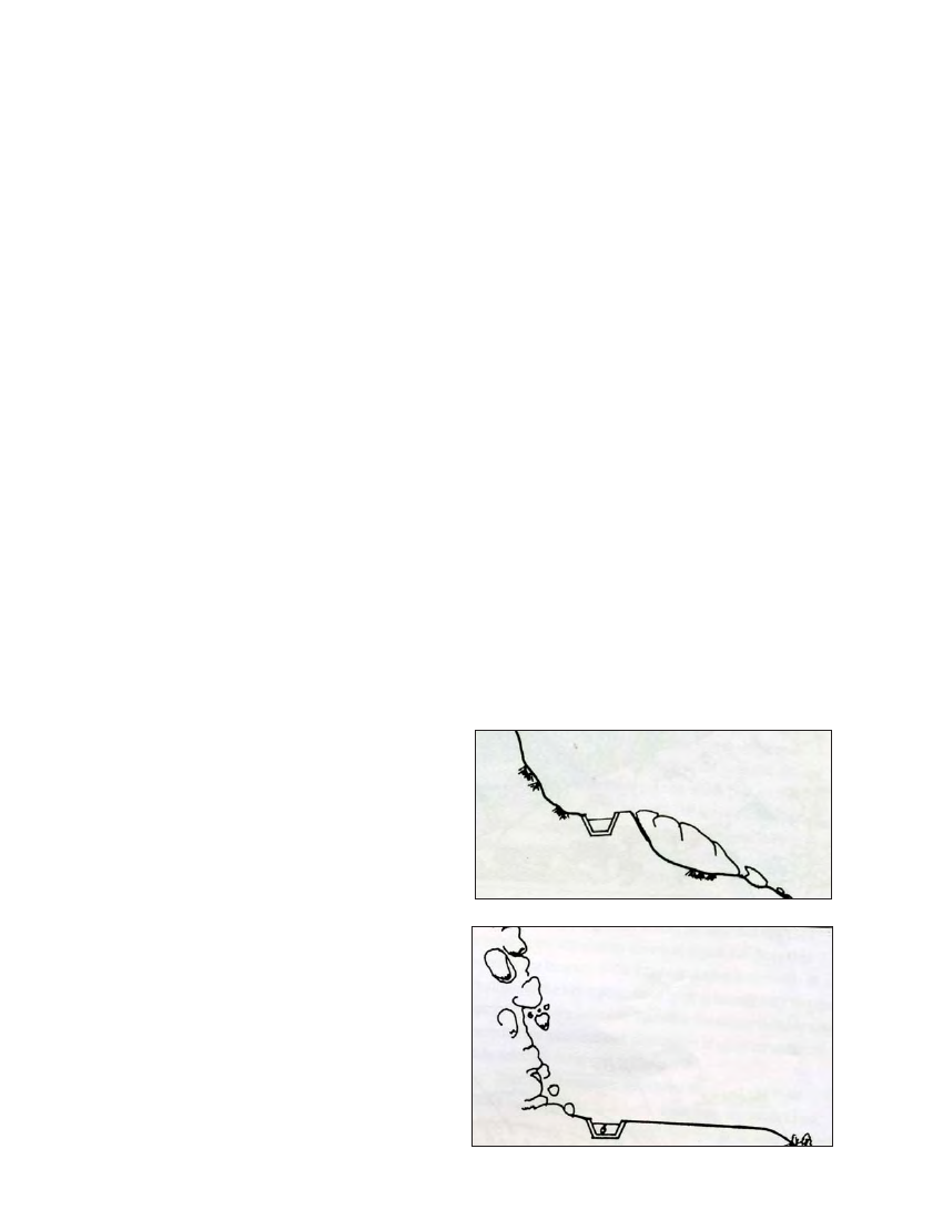
Figure 2.3 Threat to structures from below due to landslip.
Figure 2.4 Threat to structures due to falling debris from above